Forum
Important Notice for New User Registrations
To combat an increasing number of spam and bot registrations, we now manually approve all new user registrations. While this may cause a delay until your account is approved, this step is essential to ensure the quality and security of this forum.
To help us verify your registration as legitimate, please use a clear name as user name or an official email address (such as a work, university, or similar address). If you’re concerned that we may not recognize your registration as non-spam, feel free to email us at with a request to approve your username.
How to define a turbine with different blades, or one blade plus counter weight?
Quote from geerth on 25. July 2023, 22:46I want to simulate a 1-blade turbine with a counter weight that serves as a 1/2 blade at the opposite site.
I have tried to model the blade with negative station position, but that is not accepted.
If I try to design a 2 bladed rotor then QBlade assumes that the blades are equal.
Is there a possibility to define a 2-bladed turbine with different blades?
From what I understand the Chronos project assumes that I can do it with a Solidworks design and import it with a special python program, but I don’t have access to Solidworks.
For BEM analyses I would like text based definition for a 2-bladed rotor with a separate definition for each blade.
When possible: please give an example (model text file).
I want to simulate a 1-blade turbine with a counter weight that serves as a 1/2 blade at the opposite site.
I have tried to model the blade with negative station position, but that is not accepted.
If I try to design a 2 bladed rotor then QBlade assumes that the blades are equal.
Is there a possibility to define a 2-bladed turbine with different blades?
From what I understand the Chronos project assumes that I can do it with a Solidworks design and import it with a special python program, but I don’t have access to Solidworks.
For BEM analyses I would like text based definition for a 2-bladed rotor with a separate definition for each blade.
When possible: please give an example (model text file).
Quote from David on 26. July 2023, 00:29Hi geerth,
unfortunately, this is currently not possible in a straightforward way. While you can simulate a single bladed turbine in the BEM its not possible to simulate a rotor with two different blades. To my knowledge this would also be tricky to implement by the standard BEM theory.
In the structural model of QBlade it is possible to use different structural data tables for each blade to model mass imbalances or blade defects. By default the aerodynamic blade definition for each blade is always the same.
There is however a way to assign different aerodynamic data to a single blade by using the “Blade Damage” feature of QBlade, documented here LINK. The main purpose of this feature is to model aerodynamic imbalances by assigning defective polar data to an individual blade of a rotor.
You could use this to create a different aerodynamic definition for one blade of a two bladed rotor, such as assigning polars with minimal drag and lift to mimic “empty” parts of the blade as it is not possible to change the length of an individual blade.
Combined with different structural blade table data, as mentioned above you could create a dynamic model of a single bladed rotor with counterweight.
Please note that the blade damage model is only activated when performing time domain simulations in the Simulation Module, but not during steady BEM analysis (Rotor BEM, Turbine BEM).
BR,
David
Hi geerth,
unfortunately, this is currently not possible in a straightforward way. While you can simulate a single bladed turbine in the BEM its not possible to simulate a rotor with two different blades. To my knowledge this would also be tricky to implement by the standard BEM theory.
In the structural model of QBlade it is possible to use different structural data tables for each blade to model mass imbalances or blade defects. By default the aerodynamic blade definition for each blade is always the same.
There is however a way to assign different aerodynamic data to a single blade by using the “Blade Damage” feature of QBlade, documented here LINK. The main purpose of this feature is to model aerodynamic imbalances by assigning defective polar data to an individual blade of a rotor.
You could use this to create a different aerodynamic definition for one blade of a two bladed rotor, such as assigning polars with minimal drag and lift to mimic “empty” parts of the blade as it is not possible to change the length of an individual blade.
Combined with different structural blade table data, as mentioned above you could create a dynamic model of a single bladed rotor with counterweight.
Please note that the blade damage model is only activated when performing time domain simulations in the Simulation Module, but not during steady BEM analysis (Rotor BEM, Turbine BEM).
BR,
David
Quote from geerth on 26. July 2023, 11:34Thank you for this fast respons!
Before I try the “Blade Damage” feature I found a way to modify the NREL5MW model.
- I change the numer of blades from 3 to 1.
- Add the counter weight side sections and compensate the chords for section lengths
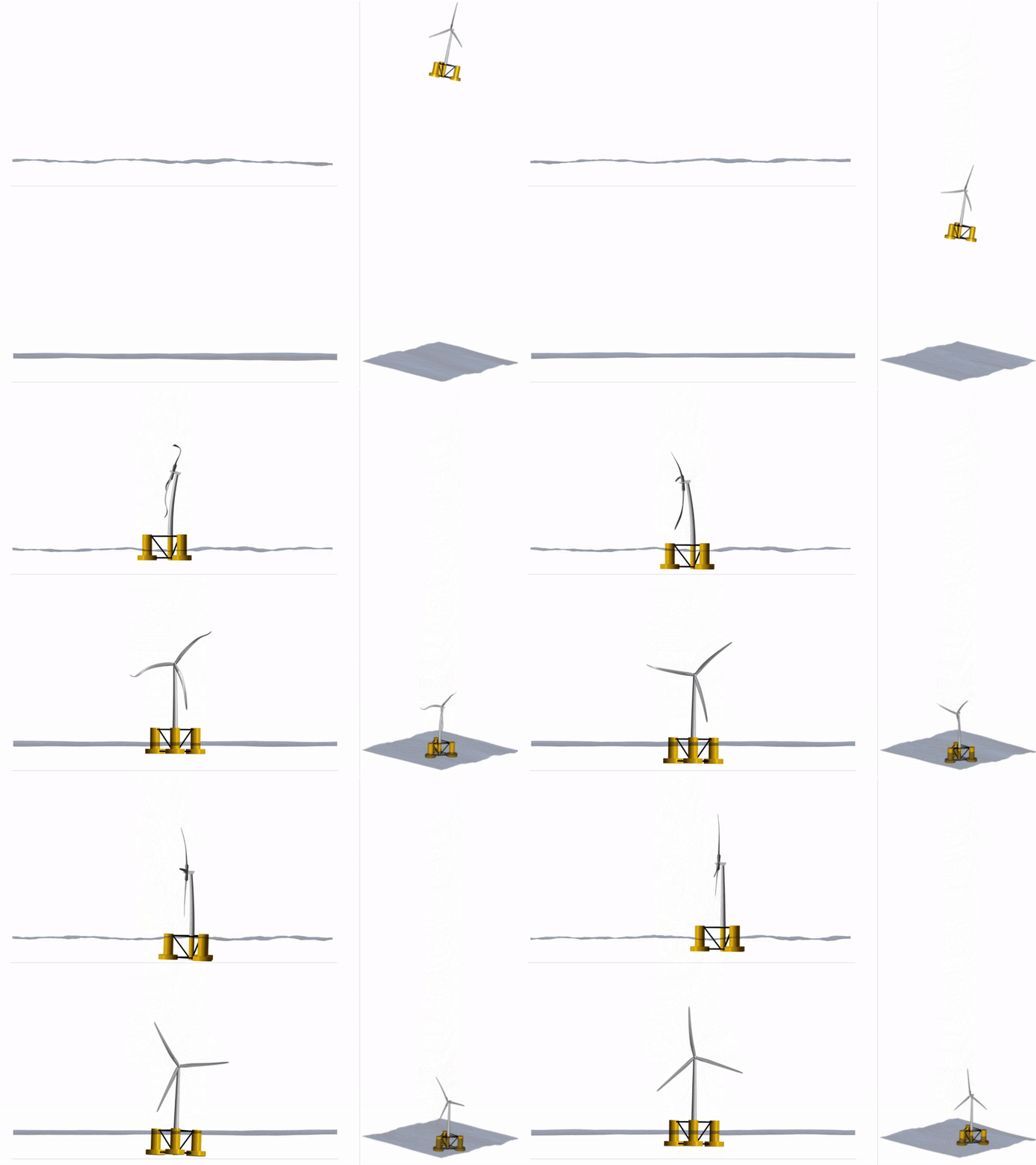
A first try (not perfect yet) shows the idea:
Thank you for this fast respons!
Before I try the “Blade Damage” feature I found a way to modify the NREL5MW model.
- I change the numer of blades from 3 to 1.
- Add the counter weight side sections and compensate the chords for section lengths
A first try (not perfect yet) shows the idea:
Uploaded files:
- You need to login to have access to uploads.


