Forum
Important Notice for New User Registrations
To combat an increasing number of spam and bot registrations, we now manually approve all new user registrations. While this may cause a delay until your account is approved, this step is essential to ensure the quality and security of this forum.
To help us verify your registration as legitimate, please use a clear name as user name or an official email address (such as a work, university, or similar address). If you’re concerned that we may not recognize your registration as non-spam, feel free to email us at with a request to approve your username.
Question about defining wind turbine rotor angle
Quote from Chris on 5. April 2025, 11:56Dear David,
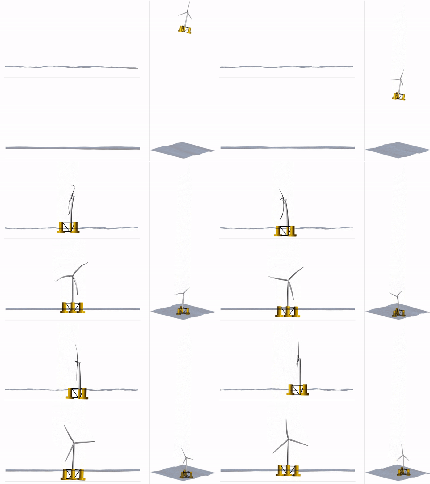
I would like to know how to define the wind turbine rotor that does not face to the global -X direction for Floating wind turbine? While keeping the coordinates definition of the platform and mooring as original X, Y and Z directions.
thanks
Chris
Dear David,
I would like to know how to define the wind turbine rotor that does not face to the global -X direction for Floating wind turbine? While keeping the coordinates definition of the platform and mooring as original X, Y and Z directions.
thanks
Chris
Quote from David on 6. April 2025, 21:06Hi Chris,
the simplest way to achieve this would be to set the rotor yaw angle in the Turbine Initial Conditions section of the simulation setup dialog.
If adjusting the yaw orientation alone is not sufficient, you can freely define the orientation of the Transition Piece (TP), which connects the turbine’s tower bottom to the floater.
Alternatively, it’s also possible to define the tower as part of the substructure file and then position the TP on top of this tower. This setup enables you to attach the Rotor Nacelle Assembly (RNA) in any desired orientation to the tower top.
BR,
David
Hi Chris,
the simplest way to achieve this would be to set the rotor yaw angle in the Turbine Initial Conditions section of the simulation setup dialog.
If adjusting the yaw orientation alone is not sufficient, you can freely define the orientation of the Transition Piece (TP), which connects the turbine’s tower bottom to the floater.
Alternatively, it’s also possible to define the tower as part of the substructure file and then position the TP on top of this tower. This setup enables you to attach the Rotor Nacelle Assembly (RNA) in any desired orientation to the tower top.
BR,
David
Quote from Chris on 15. April 2025, 04:26Dear David,
Thank you, the TP rotation works well. I would also like to know if I need to model 2 bridles mooring connecting to each main mooring line, the bridle mooring lines are connected to fairlead e.g. 3 main mooring lines and 6 bridles to fairlead, may I know the good suggestion in the modelling method? And is it possible to output all the mooring fairlead forces (i.e. 6 fairlead bridles mooring in this case)?
Thanks a lot.
Chris
Dear David,
Thank you, the TP rotation works well. I would also like to know if I need to model 2 bridles mooring connecting to each main mooring line, the bridle mooring lines are connected to fairlead e.g. 3 main mooring lines and 6 bridles to fairlead, may I know the good suggestion in the modelling method? And is it possible to output all the mooring fairlead forces (i.e. 6 fairlead bridles mooring in this case)?
Thanks a lot.
Chris
Quote from Chris on 15. April 2025, 04:32Dear David
Especially, what is the best way to define the junction of bridles (location and degree of freedom)? Is Joint Coordinate System (JNT) allow the junction of bridles freely moved?
thanks a lot
Chris
Dear David
Especially, what is the best way to define the junction of bridles (location and degree of freedom)? Is Joint Coordinate System (JNT) allow the junction of bridles freely moved?
thanks a lot
Chris
Quote from David on 17. April 2025, 14:32Hi Chris,
I would suggest to model the bridles explicitly with line elements, this has worked well for us to model bridled connections.
In the
MOORMEMBERStable, you can connect mooring members to arbitrary joints of the model. By default, when connecting a mooring line member to a joint the connection is only a positional constraint (spherical joint). Using theMOORCONSTRAINTStable, you can also add relative directional constraints, when connecting a mooring line member to a joint. See the documentation on Mooring Elements.Note of caution: During the initial ramp-up phase of the simulation, mooring lines are “relaxed” into their equilibrium position. If the initial configuration — specifically the joint placement and line orientation — deviates significantly from this equilibrium, the simulation may become unstable and diverge.
This issue can typically be mitigated by:
Optimizing the initial node placement,
Extending the ramp-up duration, or
Reducing the timestep size during initialization.
BR,
David
Hi Chris,
I would suggest to model the bridles explicitly with line elements, this has worked well for us to model bridled connections.
In the MOORMEMBERS table, you can connect mooring members to arbitrary joints of the model. By default, when connecting a mooring line member to a joint the connection is only a positional constraint (spherical joint). Using the MOORCONSTRAINTS table, you can also add relative directional constraints, when connecting a mooring line member to a joint. See the documentation on Mooring Elements.
Note of caution: During the initial ramp-up phase of the simulation, mooring lines are “relaxed” into their equilibrium position. If the initial configuration — specifically the joint placement and line orientation — deviates significantly from this equilibrium, the simulation may become unstable and diverge.
This issue can typically be mitigated by:
Optimizing the initial node placement,
Extending the ramp-up duration, or
Reducing the timestep size during initialization.
BR,
David


