Forum
Important Notice for New User Registrations
To combat an increasing number of spam and bot registrations, we now manually approve all new user registrations. While this may cause a delay until your account is approved, this step is essential to ensure the quality and security of this forum.
To help us verify your registration as legitimate, please use a clear name as user name or an official email address (such as a work, university, or similar address). If you’re concerned that we may not recognize your registration as non-spam, feel free to email us at with a request to approve your username.
Wake field simulation and output
Quote from brsnml77 on 6. September 2025, 11:45Hello.
I’m examining the wake characteristics of the NREL 5 wind turbine. During the analysis in the attached image, I noticed that the airflow velocity in the hub region is not 0 m/s. Shouldn’t there be a point in the hub region or the boundary layer where the velocity is 0 m/s? How can I ensure that the velocity in the boundary layer in the hub region is 0 m/s?
Thank you for your help.
Hello.
I’m examining the wake characteristics of the NREL 5 wind turbine. During the analysis in the attached image, I noticed that the airflow velocity in the hub region is not 0 m/s. Shouldn’t there be a point in the hub region or the boundary layer where the velocity is 0 m/s? How can I ensure that the velocity in the boundary layer in the hub region is 0 m/s?
Thank you for your help.
Uploaded files:- You need to login to have access to uploads.
Quote from David on 7. September 2025, 00:00Hi,
The influence of the nacelle on the surrounding flow velocity is not modeled by QBlade’s Lifting Line Free Vortex Wake (LLFVW) method.
The LLFVW formulation exclusively models the flow field induced by the vorticity that is generated and shed from the rotor blades. Any aerodynamic effects caused by the presence of the nacelle, such as flow blockage or wake interference, are not captured by this method.
The drag force exerted by the flow on the nacelle can be approximated using a set of nacelle drag coefficients.
Best regards,
David
Hi,
The influence of the nacelle on the surrounding flow velocity is not modeled by QBlade’s Lifting Line Free Vortex Wake (LLFVW) method.
The LLFVW formulation exclusively models the flow field induced by the vorticity that is generated and shed from the rotor blades. Any aerodynamic effects caused by the presence of the nacelle, such as flow blockage or wake interference, are not captured by this method.
The drag force exerted by the flow on the nacelle can be approximated using a set of nacelle drag coefficients.
Best regards,
David
Quote from brsnml77 on 11. September 2025, 14:33Hello.
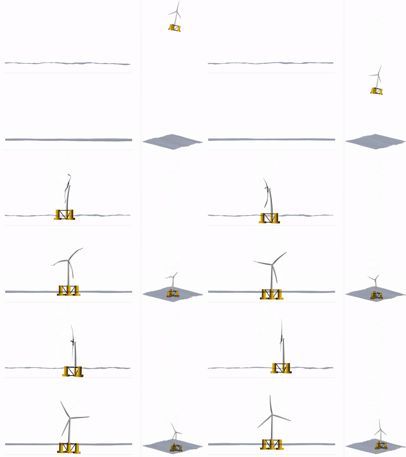
For wake analysis, I need to run a simulation at 42 RPM and 5 m/sec wind speed. During the simulation, I see the blades bending. What should I do to prevent bending? I’m only interested in aerodynamics. I can ignore structural changes.
Thank you.
Hello.
For wake analysis, I need to run a simulation at 42 RPM and 5 m/sec wind speed. During the simulation, I see the blades bending. What should I do to prevent bending? I’m only interested in aerodynamics. I can ignore structural changes.
Thank you.
Uploaded files:- You need to login to have access to uploads.
Quote from David on 11. September 2025, 17:23Hi,
From the screenshot you posted, it appears that the RPM might be too high for the turbine you are simulating.
If your focus is solely on aerodynamics, I would recommend configuring the turbine without a structural model. In this setup, all blades are treated as rigid structures.
Best regards,
David
Hi,
From the screenshot you posted, it appears that the RPM might be too high for the turbine you are simulating.
If your focus is solely on aerodynamics, I would recommend configuring the turbine without a structural model. In this setup, all blades are treated as rigid structures.
Best regards,
David


